IDF-15
Dedicated IDF cooling
Loading comparison…
R08 coordination response
Related components and specifications
Assembly candidates CSV ↓ · Scope / process CSV ↓ · Component records ↓

Communication room / design study
Start with the proposed finish-out. Compare it with the captured room, explore all 37 original notes, and review the components behind the design.

Rotate, zoom, and compare both model states.
We couldn’t open the interactive model. The rendered views remain available.
What this view shows
37 original tags / R08 geometry review
Choose a tag to read its original note and locate it in either model. A modeled concept can still carry survey and engineering items.
The source notes could not load. Reload this page or open the saved tag register.
Open tag registerLoading source notes…
No tags match. Clear the search or choose All.
IDF-15
Loading comparison…
R08 coordination response
Assembly candidates CSV ↓ · Scope / process CSV ↓ · Component records ↓
Independent design locations
Five authored locations cover the gateway, recorder, room camera and two light fixtures. These are separate from the 37 original Matterport notes; products and procurement quantities await owner approval.
Explore the completed-room concept
Explore the proposed room and its coordinated components. Source icons retain their Matterport colours; gold and cyan guides appear when Dimensions / scope is enabled. Product selections and surveys remain open.
Room dimensions and the C1 footprint follow saved Matterport annotations. Tray size and height, rack height, equipment selection, cable drops, and finish materials are illustrative concept choices. The reference tour supplies proposed security locations; 24 workstations, six Wi-Fi points, an additional IDF camera and equipment capacities are concept assumptions. The rack front is open and the near-side panel is hidden for review. Facility door cables enter the access enclosure through a separate straight 2-inch metal conduit into the ceiling. The proposed tray has a clearance offset around this riser; saved viewer guides remain unchanged. Legacy removal follows circuit identification and accepted cutover. The existing white enclosure stays visible as unresolved retention context; the retained-services control can hide it for a released-condition study. C2 is optional and off by default.
Cooling uses an authored Vertiv CoolPhase Wall WLM030A reference in the 3.5 kW class, at the published 915 × 390 × 490 mm dimensions. The proposal moves it from the narrow west candidate zone to the clear south wall for 600 mm side/front service space. The original source pin stays in place. Heat load, final capacity, outdoor condenser, refrigerant route and charge, drainage discharge/slope and electrical design remain open. Temperature and water probes do not display live readings. All 37 original notes are available above.
The clean completion model replaces the captured surfaces for presentation; it does not change the retained existing-condition scan. It is a modeled design concept, not a photograph of completed work or a construction specification.
Designed around a facility
The Pre-DEMO/RENO reference tour ↗ contains six proposed camera points, five proposed reader zones and a rear-exit monitoring point. This closet concept supports those uses, with an assumed office and Wi-Fi load.
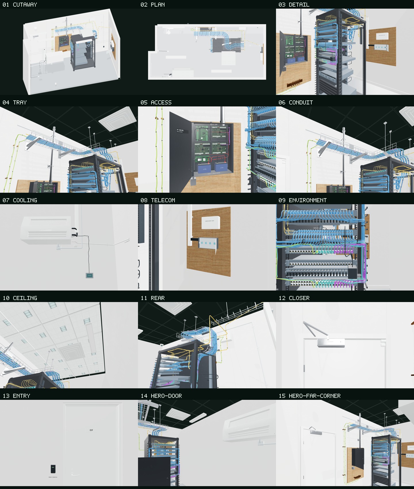
Fifteen public-lane study views use simplified original board artwork. The interactive model stays orthographic; internal full-quality documentation remains separate.
Saved review views
All fifteen public-lane posters use the accepted camera registry. Open the public-lane contact sheet ↗. The exterior reader view keeps all eight wall sections.
 From the door ↗Interior perspective still for camera-composition review. Web remains orthographic.
 From the far corner ↗Interior perspective still for camera-composition review. Web remains orthographic.
 Room overview ↗Review the rack, access-control assembly, doorway and dedicated cooling at 45-degree elevation. Near walls open to 50% edge outlines. Wall-top edges and visible fixtures retain room context; the ceiling-grid overlay is omitted from this view.
 Top view · rack and tray layout ↗Look down on the C1 rack footprint, overhead tray route and south-wall cooling unit. The roof and ceiling finish are hidden so you can compare their positions. Turn on Dimensions / scope for the saved measurement guides.
 Rack equipment · open front ↗The open rack front shows fiber and copper patching at the top, access switches and cable management below, then recording/server equipment and the UPS. This is modeled equipment capacity; product selection and procurement quantities remain pending owner approval in the component records.
 Cable tray · bends and supports ↗Inspect the overhead basket tray, wall brackets and supported bends. The tray offsets around the separate access-control conduit and sends the data bundle to the rack's rear cable entry.
 Access control · boards and power ↗The open E4M enclosure contains one MP1502 controller and three MR52 interfaces, with a FlexPower-class supply board and two 12 V batteries inside its lower zone. The bonding bar is below the backboard. Separate AC power enters the supply zone; the protected facility-door conduit enters from above.
 Door field cabling · protected conduit ↗Follow the separate 2-inch metal riser from the access-control enclosure into the ceiling. It protects the facility-door field cables; the overhead basket tray remains a separate data-cable route.
 Cooling · indoor unit and drainage ↗See the Vertiv CoolPhase Wall reference, protected interconnect, local condensate path and wall control on the south wall. The floor leak probe is at floor level. The outdoor condenser and final discharge connection remain to be coordinated.
 Telecom · separate carrier handoff ↗The east-wall backboard reserves a carrier handoff above the fiber transition hardware. The yellow fiber route rises in a protected raceway and connects to the rack independently of the access-control backboard.
 Monitoring · rack intake temperature ↗The small white probe is mounted at the rack's intake, beside the switching equipment. Its lead returns to the monitoring/PDU concept. The model shows placement and routing; it does not show a live temperature.
 Ceiling · existing air terminal ↗Look up at the existing ceiling air terminal represented within the repaired tile/grid finish. It is retained for verification alongside the dedicated cooling proposal; the scan does not establish its operating capacity or schedule.
 Rack cable entry · rear brush opening ↗The supported tray drop turns down behind the rack's solid roof and enters through a rear 1U brush opening. This is the data path; the facility-door field cables use their separate protected conduit.
 Entrance door · closer linkage ↗Inspect the door-mounted closer and articulated arm attached to the stationary frame shoe. This is a proposed hardware arrangement; final handing, product selection and commissioning remain open. IDF-14 is the entrance door contact note.
 Entrance door · exterior reader ↗View the entrance from the approach side with all wall sections kept visible, including the notch return. The reader is mounted outside the IDF beside the latch jamb at the proposed 44-inch target.
Public candidate · prepared for review · publication is not authorized.